Xiaomi Smart Camera - Recovering Firmware and Backdooring
Xiaomi Mi Home Security Camera 360° is an IP camera which has night vision, 360° PTZ control and motion detection features.
Users can instantly remote control the camera they located in their home. In addition to live video streaming, it can also do voice communication through the microphone and speaker it has.
Users can connect with the device via the Xiaomi cloud service connected mobile application (MI Home).
In this article, we will be talking about the steps we take until we get root shell access on the device.
| Model | Picture |
|---|---|
| MJSXJ09CM | 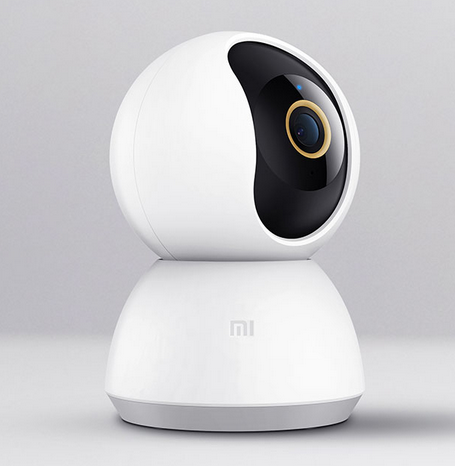 |
After installation via the mobile application, an IP address is assigned to the device. As you can see from the NMAP output, the device does not have any open port.

At this point, we could test the mobile application, which is the only place where we can interact with the device remotely. But for now we’ve decided to disassemble the device and take a closer look at the hardware. It will be useful for us if we can identifying a serial port on the board.
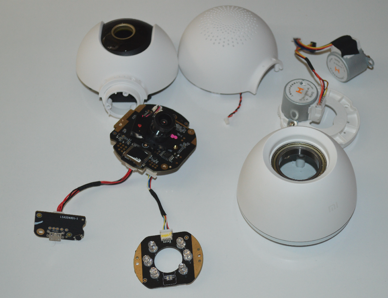
The device has a 32-bit ARM processor and 16 MB flash memory.
SoC: SigmaStar SSC323 ARM Cortex-A7
Flash chip: KHIC MX25L12833F
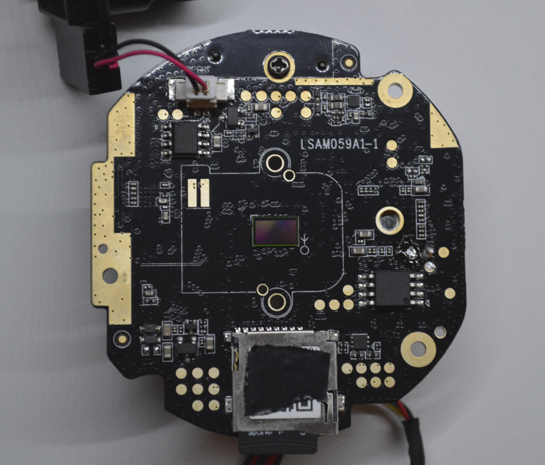
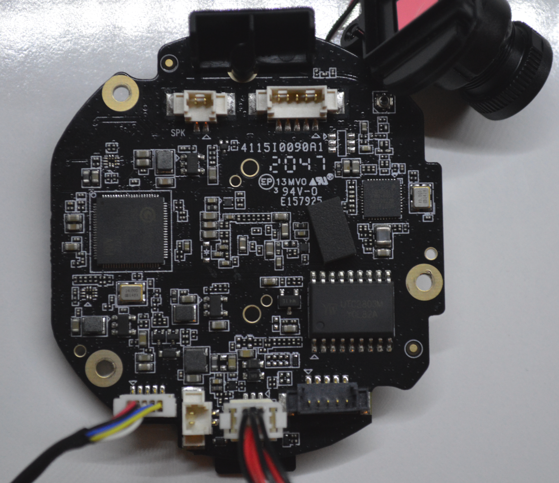
 SoC
SoC
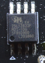 Flash chip
The MJSXJ09CM’s board is almost exactly the same as the MJSXJ05CM’s board. But the board of the MJSXJ02CM (older one) was slightly different. Inspired by the UART pins identified by the researchers on the MJSXJ02CM, we tested the pins in the same area on our own device.
MJSXJ02CM uart pins.
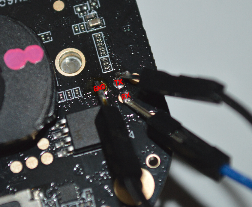
Although there is no label around the pins, we easily identified the UART pins with the help of a multimeter.
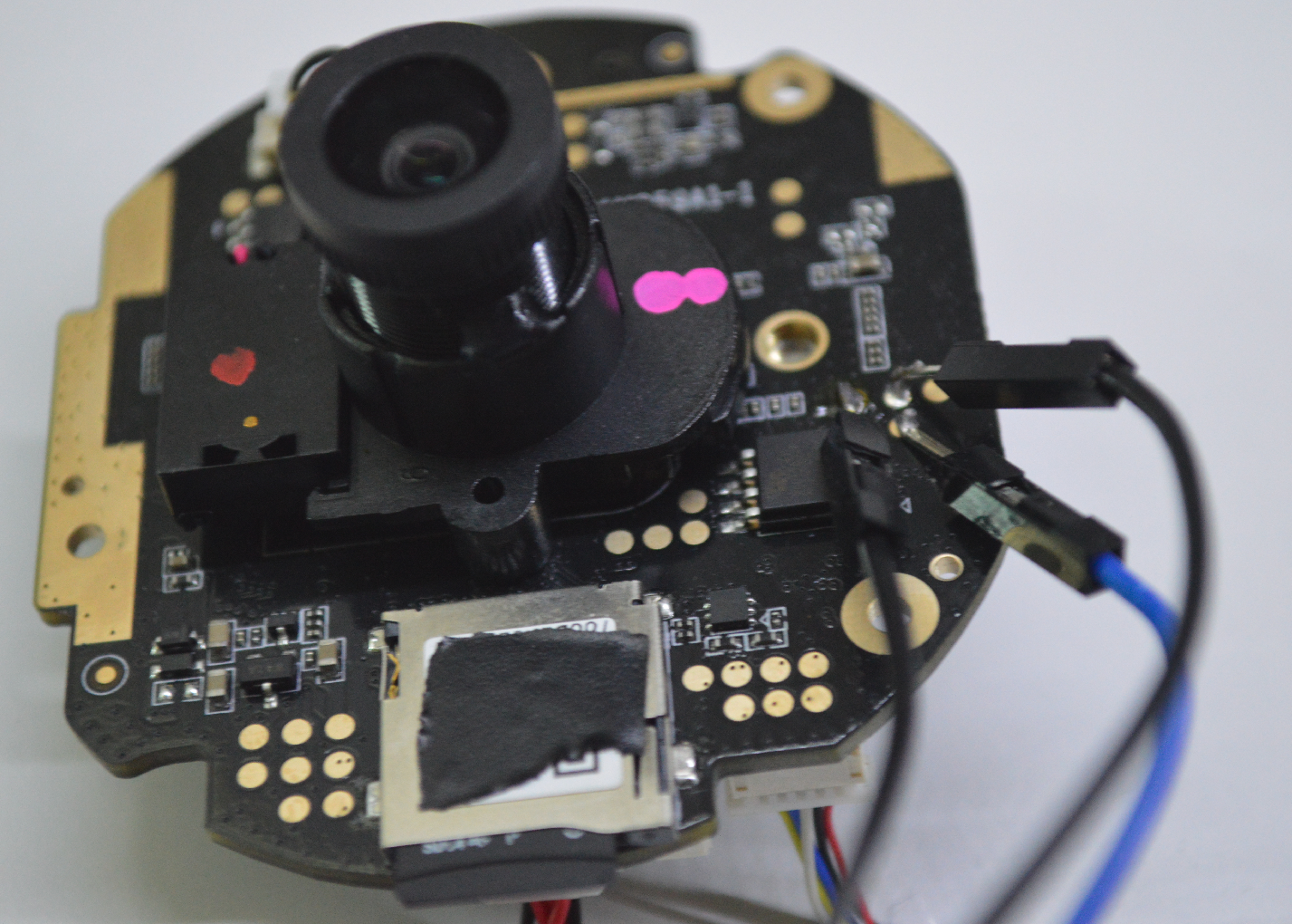
The soldered image of the TX, RX and GND pins is as in the photo.
The tool we use for the UART connection is FT232RL.
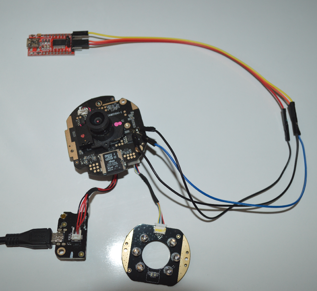
After connecting the FT232RL to the computer via USB, we started the serial communication program by command below.
UART baudrate: 115200
Terminal emulator: Picocom
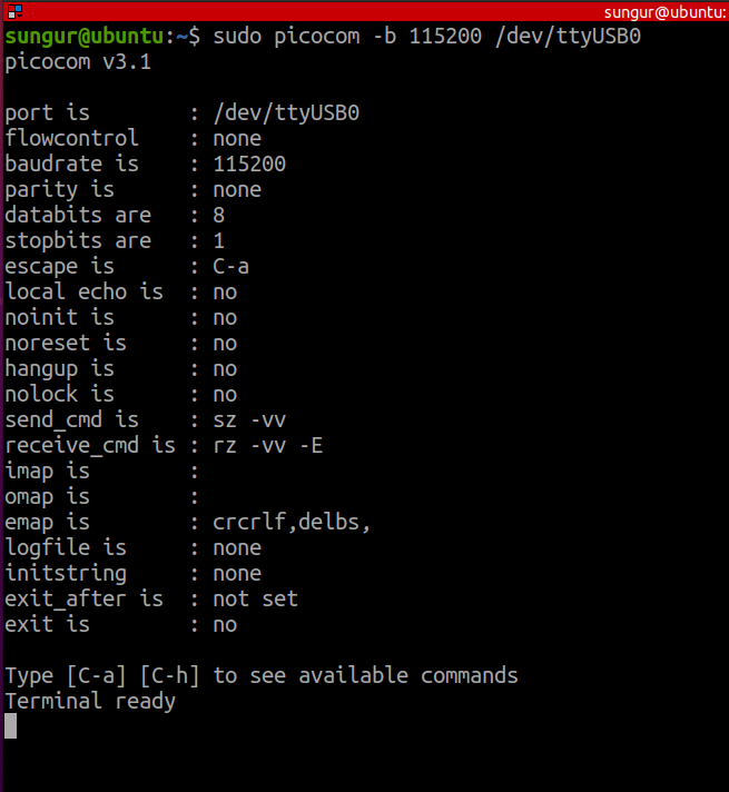
We will see the outputs of the entire Boot process as soon as we power the camera.
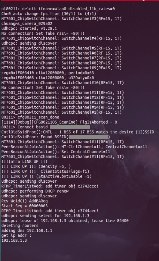
After the boot process is complete, we cannot get an active shell access we can provide any inputs.
In some cases, you might then see a prompt saying that you can press a key to activate console. Or some cases where activation can be achieved by any special key combination. Unfortunately, we were not so lucky in our case and we couldn’t get access to the easy way.
We decided to go through the bootloader. Most of the time, it is possible to get firmware with bootloader features. This device uses U-Boot which is very popular for embedded devices. As soon as the device is powered on, if you hold down the Enter key, autoboot will be stop and the U-Boot console will be active.
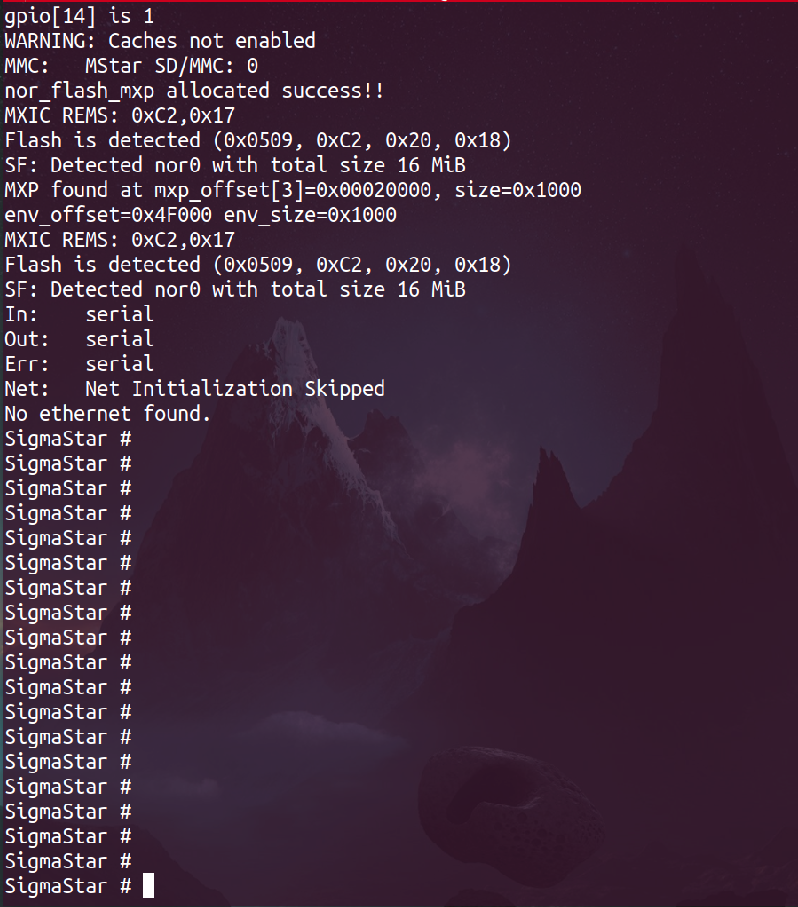
All supported commands can be listed with the Help command.
SigmaStar # help

Here you can see the boot parameters passed to the kernel.
SigmaStar # printenv

If we set the init parameter here to /bin/sh, we are telling the Linux kernel to run /bin/sh as init instead of system init. This gives us the root shell during the boot time.
SigmaStar # setenv bootargs console=ttyS0,115200 root=/dev/mtdblock2 rootfstype=squashfs ro init=/bin/sh LX_MEM=0x3fe0000 mma_heap=mma_heap_name0,miu=0,sz=0x1400000 mma_memblock_remove=1
SigmaStar # sf probe 0;sf read 0x22000000 ${sf_kernel_start} ${sf_kernel_size};bootm 0x22000000
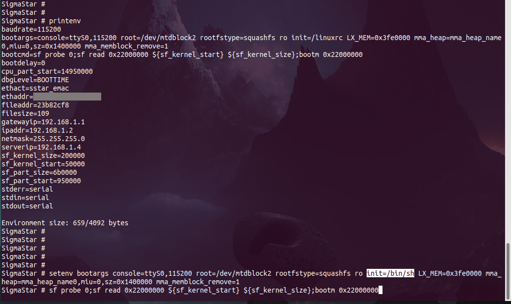
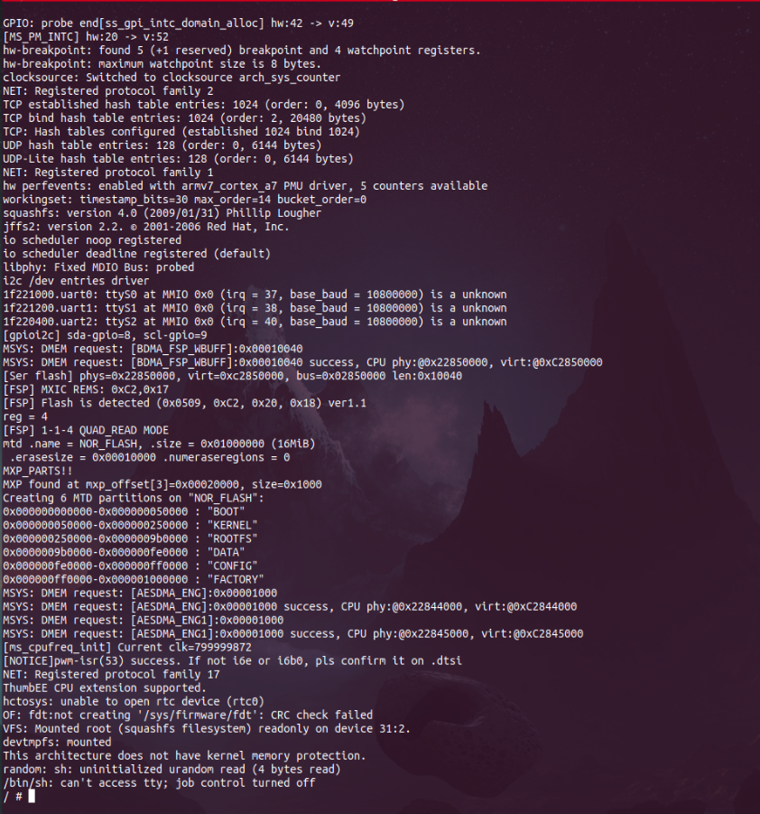

But this shell did not allow us to make changes to the system as the file system is read-only squashfs. If we had a writable filesystem, maybe we could add a script to run a telnet or ssh service on the system.
Obtaining Firmware Through U-Boot
There are several methods of obtaining firmware via the bootloader. One of them is to use tftp, which is useless in our scenario since we don’t have an ethernet interface.
Another technique is to use the very primitive memory display method. We can print the memory contents on the U-boot console using the md command. If we know the starting address of the firmware in the memory and the size, we can print all this space on the screen. The simplest way to find out this information is to look at the bootcmd parameter in the output of the printenv command.
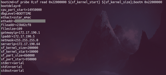
The sf read command is used to copy flash content to RAM. 0x22000000 specifies from which address in RAM the content will be copied. This was the first value we needed.
The other value we need is the flash size. We could already see this value when the bootloader first started.
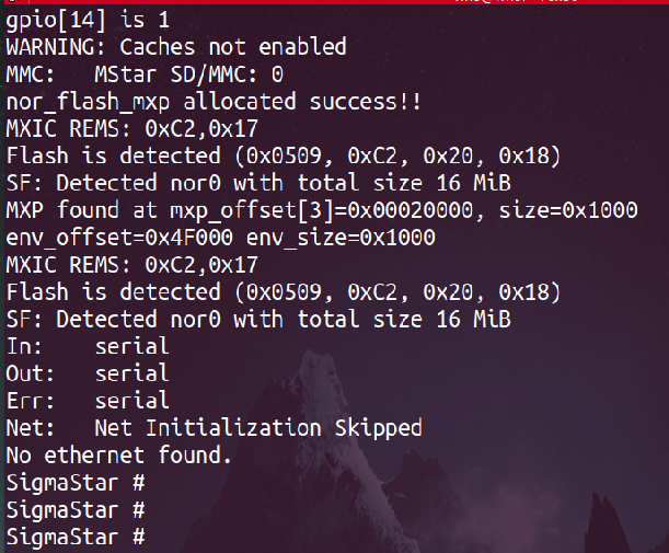
We have a 16 MB flash, which means 0x1000000 in hex.
Another way to find out the total mapped data size is to look at the partition information in the boot output.
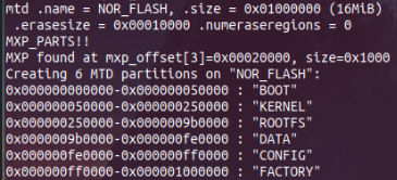
Final command for printing the all flash content:
SigmaStar # md.b 0x22000000 0x1000000
Printing to the screen will take a long time, and before doing this, do not forget to save the console output to a file.
For this, the save feature of the terminal emulator you use can be preferred. Here is the another option:
$ picocom -b 115200 /dev/ttyUSB0 | tee flash.out
We have a file with the output of the entire console (in our case flash.out). Currently this file is still not a binary file, it just contains some plain-text and hex characters. We have to manually clean the unnecessary content in this file. Only memory output should remain.
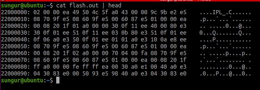
Then we need to convert this hexdump to a binary file. You can find the python code that does this conversion from here. The hex2bin.py code does this automatically. All you have to do is give the hexdump file as input and specify the name of the output file.

Finally, we have a firmware of the device. Now we can extract it with the help of binwalk and examine it.
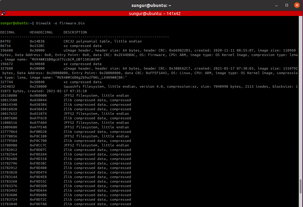

In this article, our main goal is to get shell access on the device as a priority, so we postpone firmware analysis for now.
Firmware Backdooring
We somehow got the firmware of the device, but we still couldn’t get a shell that we could access remotely to the live system. So we decided to modify the original firmware and put a backdoor in it.
First we have to extract the partitions of the firmware and then access the file system that we are going to modify.
The offsets of each partition should be added to the script. You can find these values from the binwalk output.
You can access packer and unpacker scripts on our github repo.

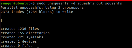
Squashfs are a compressed read-only file system and are commonly found on embedded systems. In this way, users are prevented from making changes to the file system. But after we uncompress this file system with the unsquashfs tool, we will be able to make new additions to it. Then we will create a new squashfs filesystem with these updated files.
$ unsquashfs -d squashfs_out squashfs

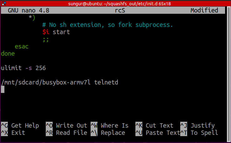
One of the best places to add backdoor is init scripts(/etc/init.d/). Because these scripts are run while the device is booting and does not require a condition. The actual init script here is rcS, and it runs files in this directory that starting names begin with a capital S, in numerical order. These are the start scripts. Likewise, the rcK script is run at shutdown.
Telnet can be used to create a backdoor, but the device does not have a telnetd binary. There is a limited version of Busybox. At this point we decided to put a statically compiled busybox on the device that supports telnetd.
The Busybox binary can be download here. We can put this binary on sdcard and run it from there.
The one-line command we added to the rcS script is as shown in the picture.
Adding backdoor is complete. Now it’s time to create a new squashfs filesystem with updated init script. The tool we will use to do this is called mksquashfs. But first we need to know the compression type and block size of the squashfs we will create. We can get this informations from the details of the original squashfs by running unsquashfs with the -s parameter.
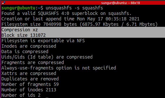
Compression is xz and blok size is 131072.
We are ready to create the file system.
$ mksquashfs squashfs_out/ squashfs_new -comp xz -b 131072
$ mv squashfs_new squashfs
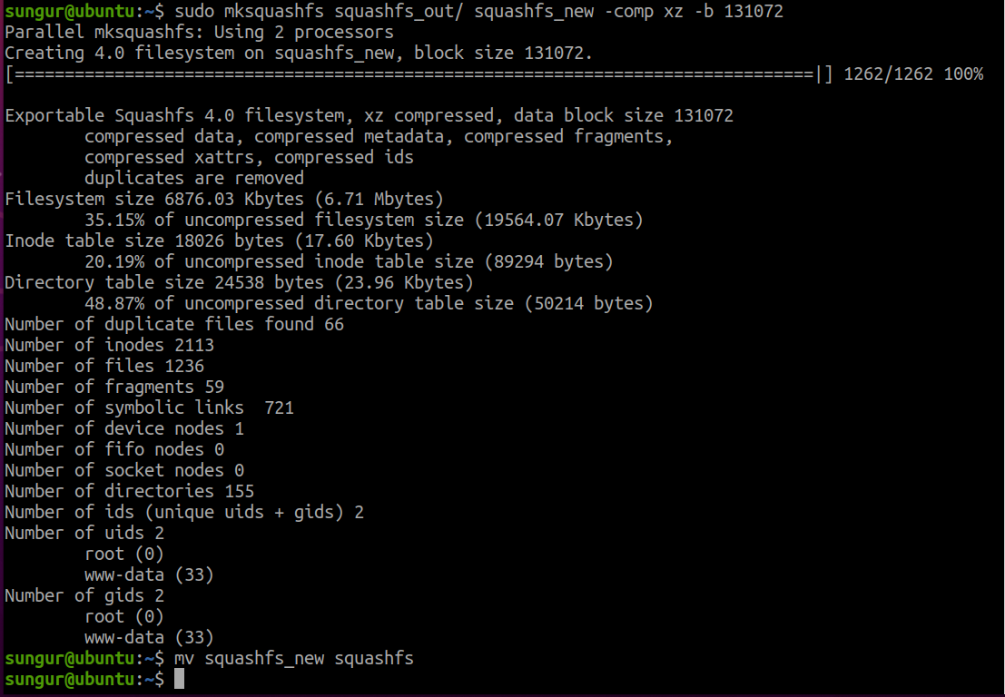
Don’t forget to replace the old squashfs with the new one.
The last thing we need to do to create the final firmware is to repack the unpacked partitions.

Now our backdoored firmware is ready.
We have 2 methods to upload the new firmware we have modified to the device. One of them is firmware update process via sdcard. The camera checking the existence of /mnt/sdcard/tf_update.img, /mnt/sdcard/tf_all.img, /mnt/sdcard/tf_all_recovery.img files in sdcard every time it boot up. We can start the update procedure of the device by placing the firmware on the sdcard (firmware has to be named tf_update.img).
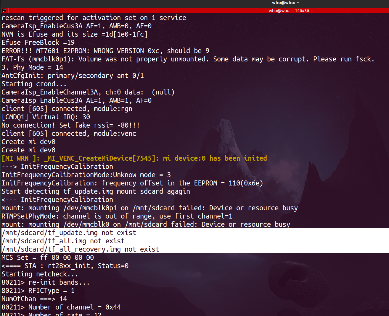
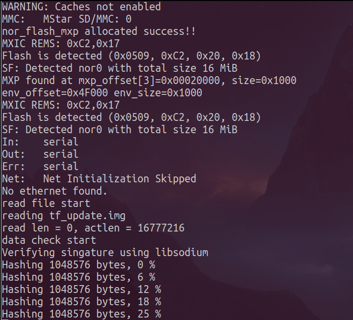
However, we were not successful in this process because the device does the signature verification of the file.
The other method we will apply in this article is firmware uploading via direct access to flash. For this, we will use CH341A flash programmer with SOIC8 clip.
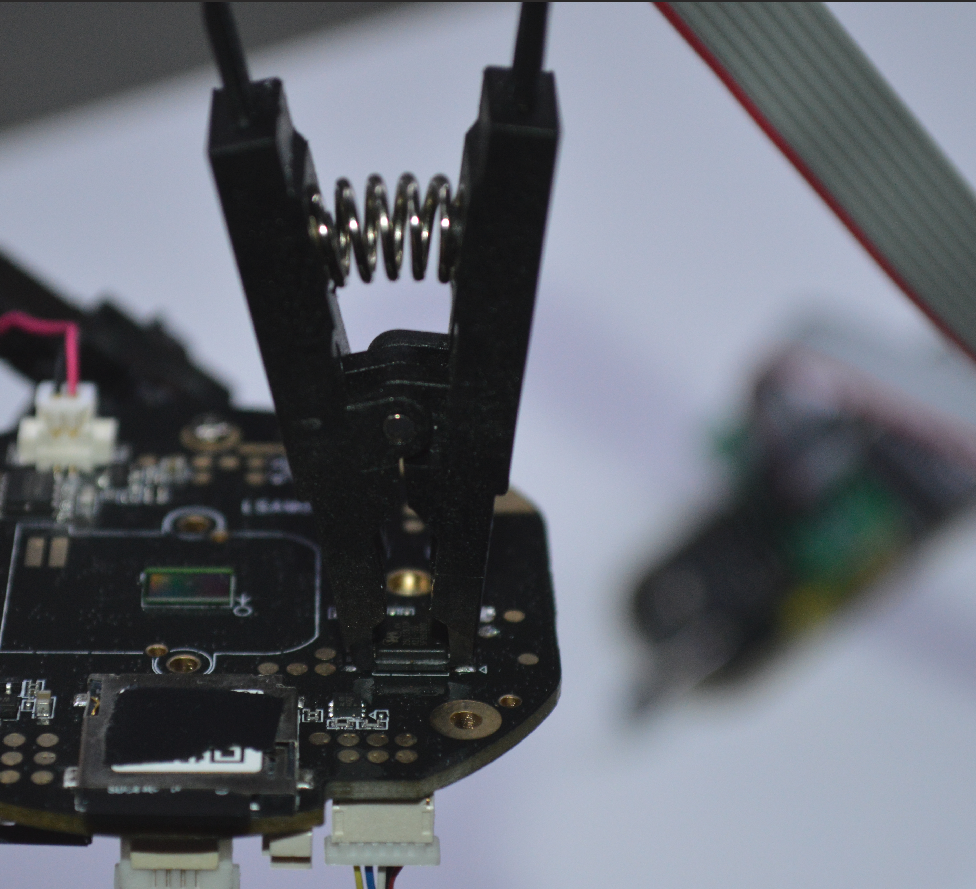
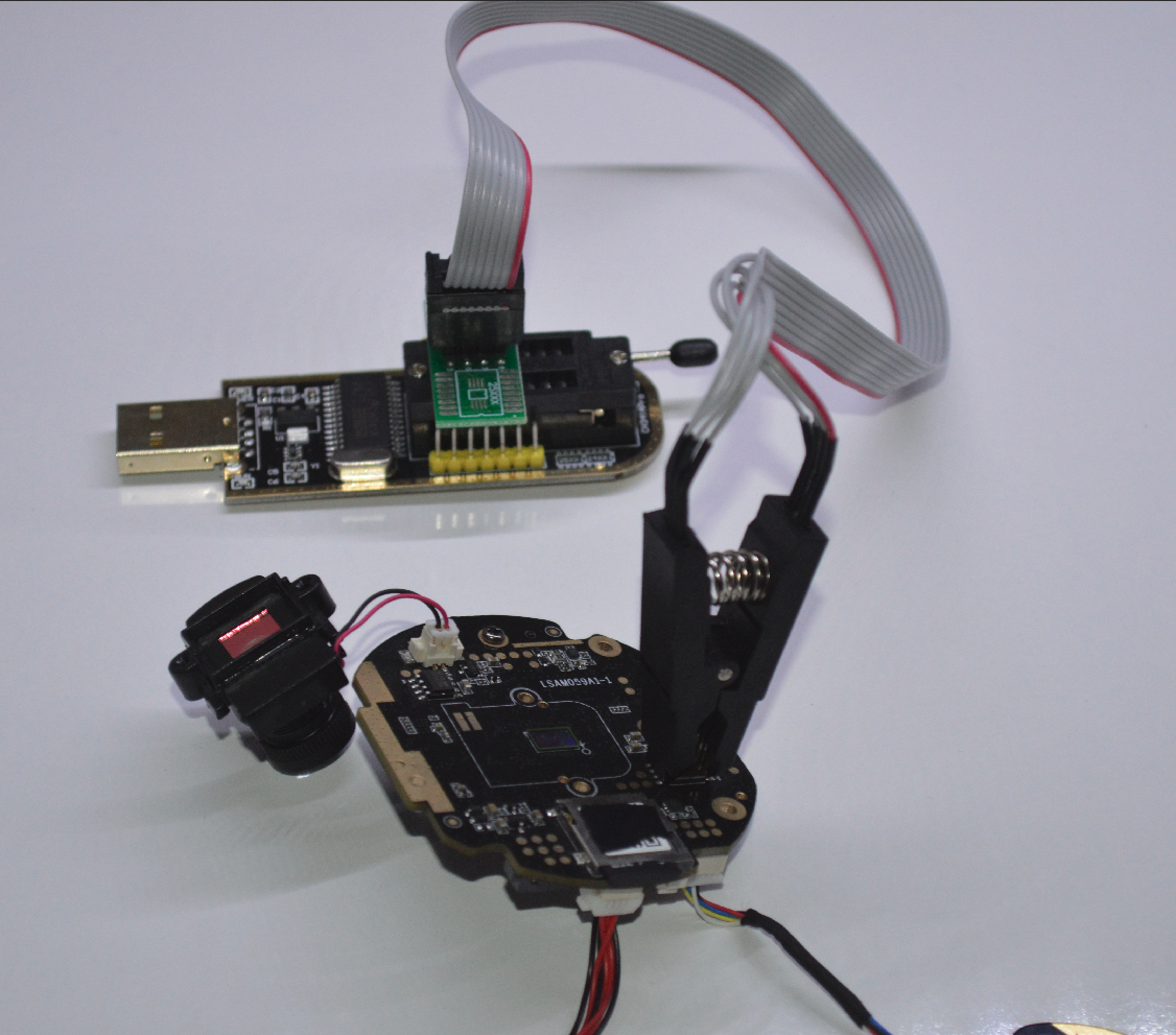
We’ll use the flashrom tool to write the firmware to flash. The -p parameter is used for the programmer name, and the -c parameter is for the flash chip name.

After about 10 minutes of operation, we have now written our backdoored firmware to flash. Now it’s time to power up the device and test if the telnet port is active.
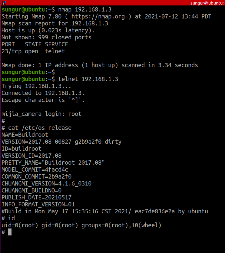
YAY! Mission completed.